Commenter Steven Newby asked for a deeper look at the Reflect node because the existing tutorials he could find on YouTube apparently only examined reflections on a sphere. In this article, we'll take a detailed look at Reflect3D and how to use it to best effect.
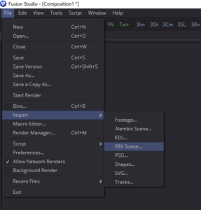 Regrettably, I'll need to use Fusion 8 for this demonstration because I'm on a loaner PC that can't run Fusion 9. I therefore won't be able to provide screenshots for the use of the new spherical camera, but hopefully my description will suffice. To get started grab this coffee cup geometry, which may be familiar from the 3d workspace chapter of the upcoming book. Import the cup and saucer into the scene using the File > Import > FBX Scene… command.
The default settings are fine, so just click OK to get five new nodes in your Flow: Two Blinn materials, two FBX nodes, and Merge3D that weds the geometry together. The scale of the geometry is a little big, so in the Merge3D, switch to the Transform tab and reduce the scale to 0.1. If you like, you can also move the Y Offset control to put the bottom of the saucer at 0. Both of those things are optional, but I find it more comfortable to work that way.
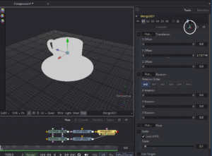 I'm not concerned with integrating the cup with a photograph this time; instead, let's see if we can't make a really nice product photo image like you might see in a catalog. We'll go for a super shiny and clean look.
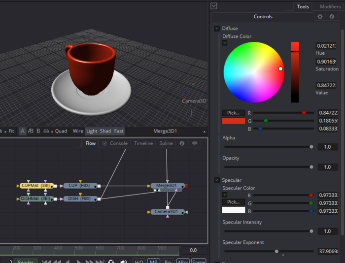
Toggle on the Light and Shadow switches in your 3D Viewer. You should now see a plain gray-shaded cup and saucer. Select the CUPMat node to adjust its settings. This is a Blinn material, which is useful for general shading, although it tends to be most widely used for relatively diffuse (or matte) surfaces. I have set mine to a brick red color and turned the Specular Exponent and Intensity all the way up to get a little more shine. I've also turned the Specular Color up to near white. Generally, non-metallic objects cast back white reflections. Only metals color their reflections. Specularity is just an approximation of reflection, so it follows the same rules.
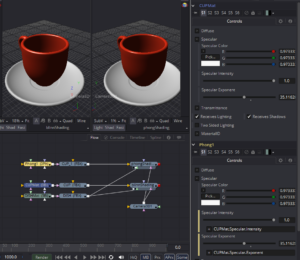 While we're playing with the shaders, this is a good time to examine the differences between the Blinn and Phong shaders. In this image, I have linked the values of my Phong to the Blinn with expressions so I could easily see how the two models differ. As you can see, the Phong (on the right) has tighter reflections, making it look a little bit shinier than the Blinn. This makes it easier to get a smooth plastic or porcelain look with Phong, where Blinn is better for stone, rough plastic, and wood. I'm going to proceed with the Phong for its better shine.
That takes care of the base material. Let's dive into getting some reflections! First, let's talk about what Fusion's Reflect node can't do. Fusion's 3d renderer is not a ray or pathtracer. It therefore cannot evaluate reflections of 3d objects on other 3d objects in a scene. The Reflect node will not show us the reflection of the saucer on the cup or vice versa. Instead, it is used to apply an environment map as reflection on an object.
Using the Reflect node therefore requires an image to serve as the environment map. This image must be mapped to a spherical environment around the object rather than being applied to the UV coordinates like an ordinary texture. To convert an image into an environment map, we use the SphereMap3D node. SphereMap requires an image with a 2:1 aspect ratio, sometimes described as a latlong or equirectangular image. Here is an equirectangular test grid that we'll use to set up the reflection:
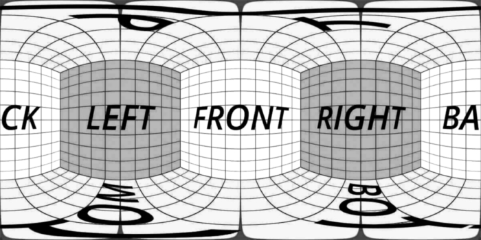
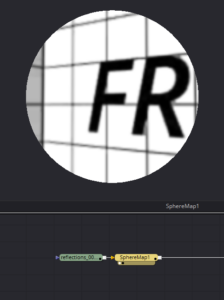 If you slot that into a SphereMap3D node and view the result, you will see that the lines have been straightened, and it appears as though you're looking through a window into a cubic environment. This environment is projected into world space and used to create the reflections we're after.
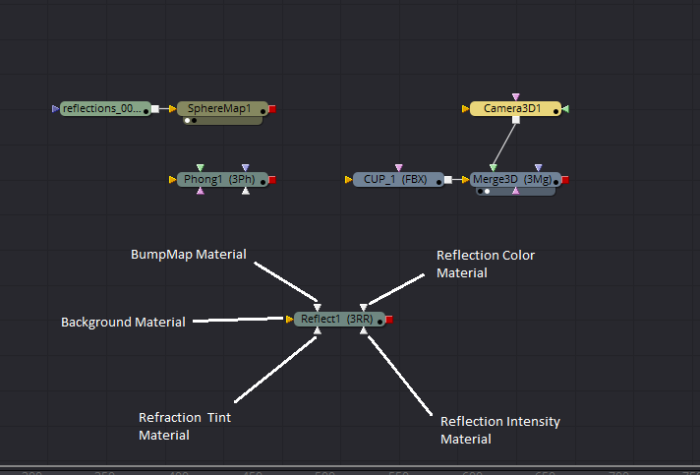
We now have everything we require to apply reflections to our coffee cup. Create the Reflect node and take a look at its inputs.
The Background Material input takes the base material of the object being shaded. In this case, the red Phong material. The reflections are applied over the top of this Background Material.
The Reflection Color Material is the colors actually reflected by the object. This input therefore gets the SphereMap. These two inputs, Background and Reflection Color, are the most important in most cases. BumpMap Material can take a bump in order to roughen the appearance of the reflection.
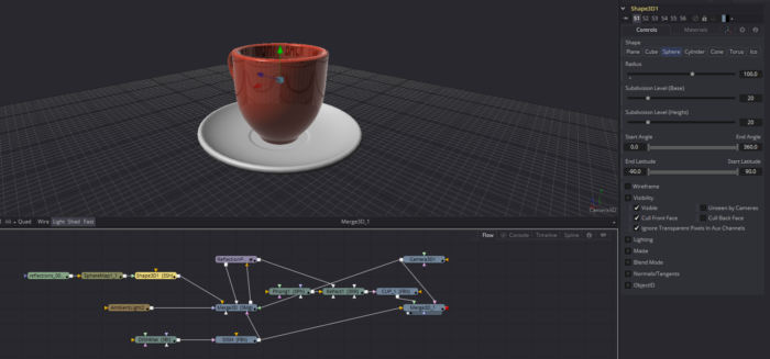
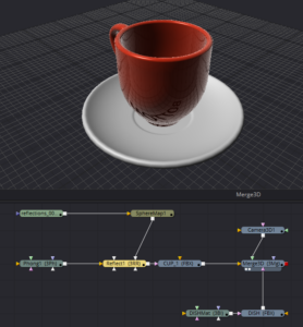 Here is cup and saucer with the Phong and Reflect shaders applied to the cup only. Notice that the saucer does not appear in the reflection, nor does it prevent the bottom of the environment map from appearing in the cup. There are ways around the problem, which we'll see in a little while.
The Reflect node's default settings give a result that is similar to a glossy surface, but not a highly reflective one. The tendency for a surface to reflect more as the angle of its surface becomes tangent to the viewer's line of sight is called the Fresnel Effect (pronounced "fruh-NEL"). Most substances exhibit this quality—it is what causes mirages; the sun reflects from distant surfaces, giving them the appearance of water, even though the sand, dirt, and asphalt are diffuse when viewed directly. The strength of the Fresnel reflections is controlled by the Glancing Strength slider. The actual reflectivity of the surface is controlled by the Face On Strength slider. The relationship between the two types of reflectivity is controlled by the Falloff slider.
The Reflect node is energy-conserving. As the Face On Strength is increased, the Diffuse value from the Background Material is reduced. If Face On Strength is turned all the way up, Diffuse has no effect at all.
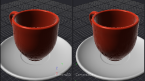 The BumpMap Material slot takes, unsurprisingly, a Bump Map. This needs to come from Fusion's Bump Map material node or it won't work correctly. Bump adds minor variation to the surface normals, giving the illusion of extra detail. The cup on the right has a Fast Noise applied as a bump map. Click on the image to enlarge it and see how the reflection has been distorted, even though the geometry itself is still smooth. The Bump Map is applied in UV space rather than world space, so it follows the surface of the object.
Reflection Intensity, like Bump, is applied by UV. It controls which parts of the object appear shiny and which dull. If you have a Specular Intensity map, you will likely want to use it for Reflection Intensity as well. If you have a Roughness map for a Cook-Torrance shader, you can use that, but it should be inverted first. Only the alpha channel counts.
Finally, the Refraction Tint Material is only used when the Background Material has an Opacity less than 1.0. In that case, the object becomes translucent, and the material will be visible and refracted through the geometry. The amount of refraction is controlled by the Refractive Index slider. Usually the same environment map is used for both the Reflection Color and Refraction Tint materials, but it's common to apply a color correction to the Refraction Tint in order to create effects such as tinted or frosted glass.
Interactive Reflection
 Okay, that's the basic usage of the Reflect node, but I promised an advanced application that lets us dodge some of the down sides, did I not?
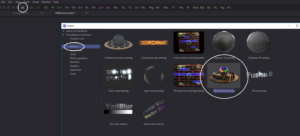
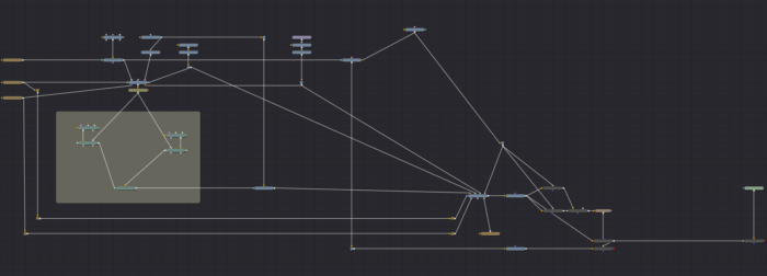
We're going to leverage Fusion's node-based nature to create a render of the 3d scene and feed it back into the same scene to create the reflections we want. Pop open the Bins and browse to the How To section. Drag the Reflections.setting icon into your Flow view to get this complicated-looking graph:
Take some time to explore it and see what it does. Of particular note is the node called ReflectionProbe, right above the Underlay. This node is actually a macro containing six cameras and six renderers with their outputs arranged into a cube map. I rather wish the devs had made it a group instead of a macro so that it would be simpler to look inside. But there are ways around that!
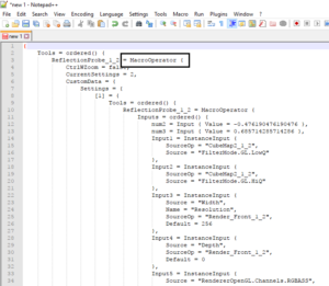 Any time you'd like to look at a macro's guts, all you need to do is change one line of its code. I recommend using a programmer's text editor such as Notepad++ for this, but any plaintext editor will do. Select the node and copy it to your clipboard, then open your text editor and paste. You'll get the image to the left. I've outlined the bit that needs to be changed. Change "MacroOperator" to "GroupOperator", then select all, copy, and paste it back into Fusion. You will get the same node, but with one difference: Now you can click the window icon on the right side of the node to expand it and see what's inside.
Six cameras, six renderers, and a CubeMap. The CubeMap node does much the same thing as the SphereMap, except that it takes six square images and maps them to the environment instead of a single latlong. By placing this ReflectionProbe macro in the middle of our scene, we can get a view of what the 3d objects look like from any point. The caveat is that the output of the probe cannot be connected to the inputs of anything that feeds it. No feedback loops.
Let's keep that copy of the probe on hand to use in our own scene and return to the example to learn how to apply it. Taking a step backward in the tree, put the Merge3D right above the ReflectionProbe in your Viewer. Here you can see the entire 3d scene assembled as we'll eventually see it. The object that is going to receive the reflections, the Sphere, has an Override3D applied to it. Select that and note that it has the property Unseen by Cameras turned on. The reflection probe must be positioned in the same place as the object that will receive its reflections. That places it inside the sphere, though, and in that position it would not be able to see anything. We therefore must turn off the visibility of the sphere. The consequence, of course, is that the sphere itself cannot appear in any reflections created by this probe.
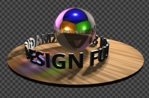 The Sphere has a second wire pulled off its output that leads to a ReplaceMaterial3D node. This node puts the reflective shader onto the sphere before passing it on to another Merge3D, where all of the scene's objects (minus the Cornell box) are again combined. In the render, the sphere shows the rest of the scene in its reflections.
Let's apply the same technique to the coffee cup to prove that it works for objects other than spheres.
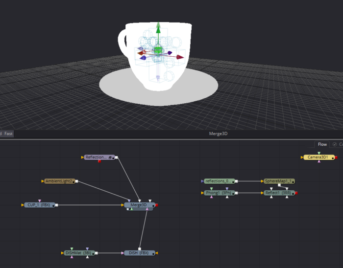
First, since we know we're going to need a render (well, six renders) of the scene for this to work, we'll need some light. To make things simple, I'm going to just use an ambient light for now. This non-directional light will look simply awful, but its purpose isn't to make the finished image; just to make the saucer visible in the reflections. Connect the ambient light to the Merge3D. As I mentioned earlier, we can't use the output of the Reflect node in the inputs of the Reflection Probe, so unhook the material input to the cup and move those shaders downstream somewhere. We'll get to them later.
Next, it's time to position the reflection probe. The controls num1, num2, and num3 control the probe's X, Y and Z coordinates, respectively. I'm not sure why whoever made this thing didn't simply name them X, Y and Z… Anyway, the Reflection Probe has two outputs. One of them is CubeMap material output, and the other is labeled Camera Placement Preview. It should be the one on the bottom of the node. Connect that second output to the Merge3D so you can see where the camera rig is, and use the num controls to position it in the center of the cup.
The example set-up used an Override3D to make the cup invisible to cameras, but that's not really necessary. Instead, just disconnect the cup and move it over with the Reflect node. Copy the existing Merge3D and paste it near those nodes, then connect both the cup and the dish to it, along with a camera if you've been using one so far. No need to bring the light along; its only purpose was to make the reflection geo visible.
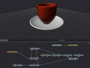 Now we need to feed the scene with the dish and the ambient light into the Reflection Probe. Just connect the output of the first Merge3D to the input on the Reflection Probe. Although it looks like this should be a feedback loop, which we wanted to avoid, if you look inside the Reflection Probe's group, you'll see that the Camera Preview output comes off of a Transform3D right before the scene is added, so in reality there is no loop here. Send the other output from the Reflection Probe to the Reflection Color Material slot on the Reflect node, replacing the existing SphereMap. Finally, reconnect the shader network to the cup and view the result in the new Merge3D.
Of course, at this point you will have noticed that we lost our environment map. We can get it back by adding a giant sphere to the scene and placing the map on that as a texture. In this image, I've turned up the Face On Strength a little so you can clearly see that the saucer is occluding the environment reflection:
This workflow is made a little faster and easier in Fusion 9 due to the addition of a spherical camera. The camera was designed for VR applications, but it serves quite well for making a reflection map. It allows you to use one camera and renderer instead of six, greatly improving the speed of the comp. This becomes particularly important if you want to also see the cup in reflections on the saucer. The setup must be repeated for the second set of reflections, doubling the number of renderers.
Another limitation of this method, and one that is much more difficult to overcome, is that the cup cannot reflect itself. That is, we'll never see the handle on the main part of the mug. I have made a few attempts to get around that, but nothing has looked satisfactory. It is also difficult to get the cup to appear properly in the dish. It tends to either occlude too much or too little of the environment map.
Still, Fusion isn't truly a 3d application, so it's unreasonable to expect it to do as good a job with reflections as a true raytracer can do.

Brian, this is amazing! Thank you so much for taking the time to put this together. I can’t wait to get home and test this out.
I see that you’re putting together a book about Fusion. I’ll definiyely be getting a copy of that when it comes out.
Hey, Bryan Ray
I render choose DNx format, the video color will darken, this is because of what? And this format can't be imported into DaVinci Resolve!!!. Is there any way to avoid it?
I don't know. My advice is to never render to a video format from Fusion; it's not the best tool for the job. I always convert video formats to frames and only render frames from Fusion. It's far more efficient, and there are better ways to convert frames back to video.
OK, I see what you mean, but I also want to know which format frame will be rendered to maximize the quality of my finished product? Because I think if the JPG format that will compress to 8bit, the quality of compression is serious. How do you usually do it?
Oh my, definitely *not* jpeg! I recommend taking a look at this article: http://www.bryanray.name/wordpress/anatomy-of-an-image/
The end goes over several common image file formats with their advantages and disadvantages. The short answer is that Resolve was built to use DPX, a 10-bit uncompressed format. The other most likely choice is OpenEXR, which has an option for lossless or lossy compression and comes in both 16- and 32-bit flavors.
DPX is usually assumed to be logarithmic, and EXR is assumed to be linear. If you're outputting rec709 or sRGB, you may have to do an extra step in Resolve to define your actual color space (I've only opened Resolve once, and I wasn't dealing with a Fusion export at that time, so I don't have a clue about that end of things).
OK, I will look at this article, thank you for your answer, it is very helpful to me.