Fusion 9 has been released, and the retail price for the Studio version has dropped to a mere $299. From this article forward, I'll be using Fusion 9 Free on Windows 10. Although the new price point makes Fusion Studio more accessible than ever, I will continue with the assumption that the student is using the Free version. Studio-only features may be detailed in supplemental chapters on the website.
In the previous chapter, we used Fusion's 3D system to match the position and angle of view of the physical camera used to take a photograph. We also did a little bit of grain and focus matching to help integrate the coffee cup into the plate. In this chapter, I'd like to expand on those ideas by discussing the various qualities and defects that film and video cameras produce and how to mimic them for the most convincing composite possible.
I have arranged these concepts roughly in the same order that they affect the image. When setting up a composite, it is helpful to arrange your nodes in a similar order in order to maintain realism. For instance, you wouldn't want to perform a lens distortion before the camera shake because the lens is attached to the camera and will therefore shake with it. Likewise, grain should be applied after all optical effects because it is a property of the sensor or film and therefore affects almost everything, including such things as lens flares and blur.
Physicality
Camera Tracking
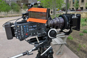
In the previous chapter's tutorial, we matched the camera's physical orientation by eye. More advanced workflows may involve tracking the camera's motion in addition to merely positioning it. Simple pans or tilts can be matched with a 2d Tracker, but more complex motions need specialized tools that can analyze the scene and recreate the camera's motion. Fusion 9 Studio includes a Camera Tracker that can accomplish this feat. It works by placing 2d tracking points on many features simultaneously, analyzing the way they move relative to one another, then creating a solution for a moving camera that accommodates all of the tracking points.
While Fusion's Camera Tracker does work well for many shots, it is not as powerful as software dedicated solely to the task, such as PFTrack, 3D Equalizer, Syntheyes, and Boujou. These programs have many specialized features to make camera tracking faster and easier, and they have tools to solve very difficult scenes.
Since Camera Tracker is only available in Fusion Studio, there is no tutorial for it in this book. Keep an eye on the website for supplemental chapters and tutorials that address this and other advanced features of the Studio version.
Animation
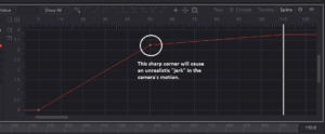 There may be times when you aren't matching to an actual camera, but you still want the feeling of a physical camera. The trouble with animating a CG camera is that it often feels too synthetic. Real cameras don't move perfectly. They don't accelerate instantaneously. They can't perform some of the acrobatics that a virtual, animated camera can do. When you're animating a camera, keep these things in mind.
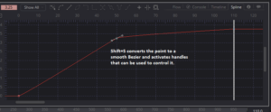 Smooth out the sharp corners in your animation splines to account for inertia. Keep in mind what kind of mounting the camera might be on and what the limitations of that mount are. A camera on a crane doesn't usually move in a straight line—it move in an arc. A camera on a dolly does move in a straight line, not in a curve. Although you have six degrees of freedom with your virtual camera, it is a good idea to act as though you do not.
Shake and Vibration
Cameras attached to cars, helicopters or people usually have some degree of shakiness. A perfectly smooth road is rare, and the motor of the vehicle itself will usually impart its own vibration as well. Much of the time, you will be asked to stabilize footage to remove this shake, but sometimes it is useful to add some to give life to an otherwise static shot, particularly in a high-energy action scene. Fusion has a Camera Shake node that can add shake to a 2D image, or you can use the Shake modifier on any control to add some chaos to an animated Camera 3D. The shake parameters can themselves be animated if you need the camera to respond to an explosion or something of the sort.
Lenses
The lens assembly of the camera gathers light and bends it, focusing a smaller representation of the scene onto the camera's film or sensor. This bending creates several artifacts in most images. Sometimes you will be called upon to remove these effects, and sometimes you'll need to match them. Very often, you will be required to do both in order to match elements shot with one lens to a plate shot with a different one. In addition to the refractive artifacts, a camera's lens is, in fact, several lenses all working together. Each such lens has two surfaces, and those surfaces can create their own artifacts. There might be scratches, moisture or dust on the surface of the outer lenses. The interior ones sometimes create reflections or flares.
Dust and Scratches
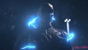
It is all but impossible to completely prevent dust from adhering to a lens. The nature of electronics and static electricity ensures that the glass will attract particulates. Further, if the lens is not well taken care of it may have scratches. Usually a lens with an obvious scratch will be retired, but some micro-scratches may not be apparent except under specific circumstances. Dust and scratches will usually show up if light is just grazing the lens. The imperfections will be reflected into the lens assembly, creating spots in the image. Depending on the job, you might need to remove these spots, match them, or even create them where they otherwise don't exist. The Flash television series on The CW uses synthetic lens dust as a stylistic element to enhance the character's lightning-like Speed Force effects.
Dust-busting, the discipline of removing dust and scratches from an image, is a more focused and subtle variation on creating clean plates. The process we used to remove raindrops from the lens back in the Clean Plates chapter is a good example.
Creating dust can be done with particles and some keying techniques.
Flares
Lens flares are quite possibly the most egregiously overused effects elements there are. J.J. Abrams notwithstanding, frequent and obvious flares have long been regarded as the mark of amateurish CG.
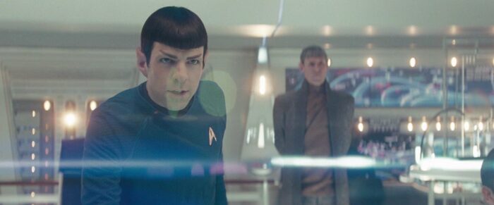
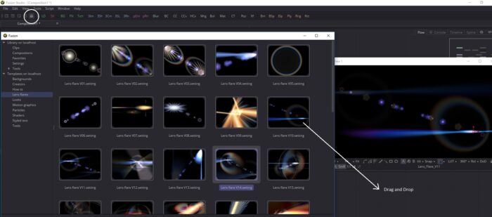
It is not uncommon for compositors to be called upon to paint out lens flares. Other times, you might be asked to match a flare that was captured in camera or to add one to help sell a bright CG effect. Fusion has a tool called Hot Spot that can be used to simulate flares, and there are several instructive examples available in the Bins. The Bins are a place where templates and presets can be stored for easy retrieval. They come pre-loaded with numerous samples to learn from. I'll talk more about the Bins in the next chapter on Customization and Pipelines.
A lens flare occurs when bright light enters the lens and is reflected by internal components. The light may reflect and be refocused several times, which is why flares can be so complex, with many spots and shapes.
 The light that causes a flare need not be visible in the frame. A strong ray entering from the side can create a flare, too. In this image, the sun was well outside my field of view, but my lens reflected the glare into the sensor.
Because the flare is happening inside the lens, it is always superimposed over the rest of the image. No object can occlude the flare itself, although if something occludes the light source that is causing it, the flare will vanish. This can make it difficult to integrate other images into a shot with a strong lens flare. Imagine trying to put a CG hummingbird into my photograph—the flare would have to be painted back in over the bird without bringing back any of the trees.
Flares can be very subtle in both motion and color. It is sometimes difficult to see one when looking at a single frame. It takes much care and patience to match a lens flare. Sometimes it's easier to remove it entirely and apply a new CG flare to replace it, but you must take care to match the character of the original artifact as closely as possible.
Focus and Depth of Field
A lens is not always capable of keeping everything in a scene in focus. How much of the image is in focus depends on the available light, the efficiency of the lens, the distance from camera to subject, and the focal length. The choice of how deep the field of focus is usually a creative choice—most cinematographers will shoot a landscape with a very large field, keeping everything in focus, but a dramatic close-up might be very shallow.
There may be other creative decisions regarding focus. A rack focus moves the focal plane during a shot to direct the viewer's attention between foreground and background. And sometimes a shot is simply out of focus because someone made an error. Unlike many of the lens artifacts I've mentioned, it is not usually possible to remove a focusing error—an image that's blurry cannot be made sharp. It is pretty easy to turn a sharp image blurry, though, and it's something you will do frequently to match your elements to the primary photography.
 One side effect of a defocused picture is that bright spots tend to bloom out and form the shape of the iris. The particular quality of the out of focus areas is called bokeh (this is a Japanese word, pronounced "boh-kay", with equal stress on each syllable). Notice how the blooming bright areas in the background have a pentagonal shape.
Fusion's Blur tool can perform very minor blurs, but to get better results, you'll need the Defocus tool instead. Even better results can be had if you have Fusion Studio so that you can use the Frischluft Lenscare plug-ins.
Lens Blur
No lens is perfect, and the less money is spent on the glass, the more artifacts it will create. One notable effect of using a low-quality lens is the blurring that occurs near the edges. The accompanying image is a crop from a 70mm film frame. The right side of the image is from the center of the frame. Notice how sharp the Contemporary Arts Center is in comparison to the buildings at the left edge of the frame.
In order to integrate a CG building into this scene, the variable blurring must be accounted for. In this particular shot, we added a new building right in front of the Contemporary Arts Center, which the helicopter flew over. As the building approached the bottom edge of the frame, it needed to be blurred progressively more to match its surroundings. Fusion's VariBlur node can be used to match a blur like this one.
Vignette
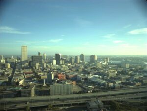 Maximum light collection occurs in the center of the lens. Near the edges, the lens becomes less efficient, resulting in a slight darkening near the sides of the frame. Vignette is another artifact that is frequently accentuated as an artistic choice, as it naturally directs attention toward the center of the picture, where the most important action is usually happening.
This is a particularly extreme example, caused by using as much of the film as possible while still maintaining a rectangular frame. In fact, you can see in the upper corners that the crop was, in fact, a little too wide, revealing the edge of the aperture itself. The aperture is the gap through which light passes; its size is controlled by an iris.
Distortion
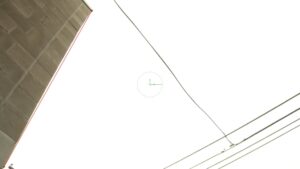 Lens distortion is most obvious when a lens is either extremely short (wide angle) or extremely long (telephoto). In the former, the sides of the frame get pushed outward, creating barrel distortion. In this image taken from the Clean Plates chapter, you can see that I have superimposed a straight polyline, which shows how the corner of the building appears to have a slight curve. You may recall having to slightly adjust the Bezier handles of the Grid Warp to account for the curve when making the clean patch.
A telephoto lens does the opposite: pincushion distortion, where the sides of the frame are pulled inward. Some complex lenses may even exhibit both of these forms of distortion—one at the edge and the other near the center of the lens. Fusion is capable of handling any of these circumstances with its Lens Distort node. Lens Distort has several modes corresponding to the distortion models in the major camera tracking programs.
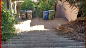
Distortion should be removed from an image prior to camera tracking in order to get the best possible result, but the final composite should use the original, distorted plate, and any necessary distortion should be applied to the elements. The reasons for this are two-fold: First, undistorting the plate will slightly soften it. Any unnecessary degradation of the plate is absolutely to be avoided. Second, undistorting will require a crop to preserve the rectangular shape of the frame. Removing barrel distortion either pushes the sides inward or pulls the corners outward (preferred since it preserves the center pixels). Removing pincusion distortion either pushes the corners inward or pulls the sides outward. Either way, you wind up with a non-rectangular frame that must be cropped, throwing away your client's precious pixels.
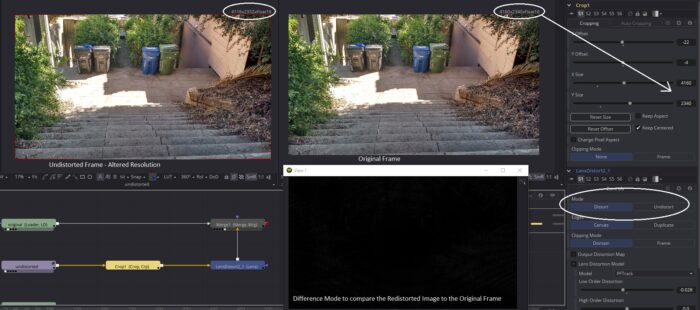
You should perform tests on your plates to determine the proper workflow for distortion. For instance, PFTrack's distortion values are based on the original image resolution, but its undistorted image will be larger than the original image. To test your distortion workflow, bring both your undistorted and original plates into Fusion. Use a Crop node to set the resolution of the undistorted plate to the same size as the original plate. Make sure that Clipping Mode is set to "None" so you don't lose pixels that fall outside of the new frame size, and the Keep Centered switch should be checked. Add a Lens Distort node, set the mode to Distort and enter the values provided by your tracking software. Compare the redistorted frame to the original using a Merge set to Difference. The result should be mostly black, with some inaccuracies due to filtering.
When you are satisfied with your redistortion workflow, you can use the crop and Lens Distort nodes to process your CG elements.
Exactly what information you receive from your matchmove department can vary. Sometimes you will get distortion parameters usable like you see in my screenshot. Other times you will get a distortion map (sometimes called an ST Map after the Nuke node that is used to handle it in that software). This map can be used with the Displace node with Type set to XY. The Displace method is not as accurate as the Lens Distort node, but it does have the advantage of working with lens models that are not supported by Lens Distort.
Some free career advice: Lens distortion is a topic that is not well understood by most junior and mid-level compositors, and many facilities lack standardized workflows. If you have a firm grasp of the interactions between different matchmove and compositing programs, you will quickly become a prized team member.
Aberration
The index of refraction in a medium varies with the wavelength of the light that passes through it. Blue light, with its very short wavelength of 470 nm will be bent more than red at 680 nm. As a result, near the edges of the glass, where the light is bent the most, the channels may separate slightly, resulting in colored edges. This phenomenon is known as chromatic aberration.
Aberration is relatively easy to simulate—a very tiny Scale of only one channel will accomplish it. Most of Fusion's tools can be limited to operate on a single color channel by going to the Common Controls tab and unchecking any channel that you don't want to operate on. Two Transforms, one operating on Red and the other on Blue, can be used to Scale the channels to create the fringing. Usually you'll want to scale Red up slightly and Blue down. Alternately, you could scale both Red and Green up, but since Green carries most of the detail it's not the best idea to scale it if it isn't necessary.
Reducing aberration is a trickier proposition. It's a side-effect of lens distortion, so using a Lens Distort tool operating on the problem channel(s) is usually the best method. Sometimes a small translation of a misaligned channel may also be necessary. It usually takes a great deal of patience and time to address an aberration problem, and sometimes it's not possible to eliminate it entirely because light is a continuous spectrum, and not all of the scatter in a given channel will be of the same magnitude and direction.
Sensors and Film
After the image has passed through the optics, it passes through a shutter, which rapidly opens and closes to control the length of exposure for each frame, and the gate, a rectangular mask that determines the physical size and aspect ratio of the recorded image, before striking either a piece of film or a digital sensor.
Noise
A digital sensor creates an image by measuring the number of photons that strike it, creating a charge in a capacitor or diode. The more light, the greater the number of photons, and the greater the charge. Random small differences in charge from one pixel to the next create noise in the image. This noise can come from both the electronics of the camera itself and from simple statistical variation in the number of photons striking each pixel. Higher quality electronics (more expensive cameras) can reduce the first source. Higher sensitivity settings (ISO or ASA) can reduce the latter, at the cost of a lower shutter speed and thus greater susceptibility to motion blur. Larger sensors and higher resolutions reduce noise from both sources.
The average variation in brightness due to noise is uniform across all the pixels, regardless of the value they hold. The magnitude of the variation is called the noise floor. Noise is most visible in dim parts of the frame because as the brightness increases, the ratio between the level and the noise floor does as well. It's easier to see the difference between 0.01 and 0.02 than it is the difference between 0.83 and 0.84.
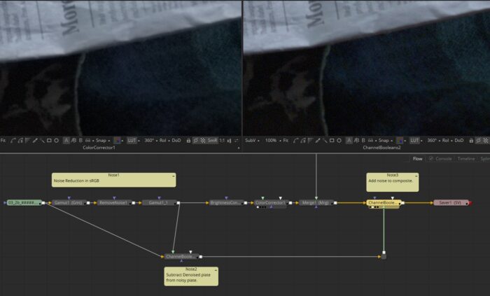
A typical first step in many compositing workflows is to remove the noise or grain from the clip. The work is done on the noiseless image, and just before rendering, the noise is either restored or new synthetic noise is applied. Ideally, the image is returned to the client with as many unchanged pixels as possible, meaning that the original noise should be used whenever it is practical.
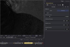
Fusion's Remove Noise tool is not quite adequate for a high quality noise reduction, but if it's all you have, it's all you have. I recommend using Chroma mode with small values for Softness Luma. Otherwise, the image gets much too blurry. Detail Luma will bring back some of the sharpness, but you'll still lose edge fidelity. You can turn Chroma all the way up without harming the image too much. If you have Fusion Studio, consider purchasing Neat Video. It's pricey, but there's nothing on the market that does a better job. For both noise reduction tools, apply them in sRGB space rather than linear; they seem to work better that way.
Once you have your reduced noise image, subtract it from the original using a Channel Booleans in Subtract mode. Make sure your images are in floating point because you will need the negative values that result, and they'll be clipped if you're in integer. Carry the result of your Subtract all the way to the end of your composite and use another Channel Booleans to Add it to the finished image.
Adding the original noise won't always be the best choice. Details are often carried in the noise, and if you've spent time painting something out, you don't want to add a ghost of it back in by regraining. In addition, if something has been added to the shot, the grain might have the wrong luminance. In such cases, you can use the Film Grain tool to create synthetic noise that is laid over the entire image. When using Film Grain, take care to closely match the properties of the original grain in each channel as well as when looking at the full color image. I will talk about this tool in more detail in the next section about grain.
There is also a hybrid approach in which you perform a hard difference key between the denoised plate and the final composite, then use it as a mask to determine which pixels receive the original noise and which receive the synthetic. If you use this method, it is even more critical to match the exact qualities of the original grain so that the new elements are not obvious. Depending on the nature of the shot, it is also sometimes practical to simply use the original plate as-is—no denoising—and add noise only to the elements.
Grain
The light-sensitive element of a piece of film is a layer of tiny particles of transparent silver halide. When struck by photons, these particles turn into opaque silver, darkening the film and creating the negative. As with the digital sensor, there is some statistical variation in the number of photons that strike individual silver halide crystals, and there is also variation in the sensitivity of the crystals themselves. This negative is developed, then turned into a positive projectable print using similar chemistry (I'm leaving a lot of steps out here for the sake of clarity—consult a good book on film editing for more details). This step adds still more variation in the silver particles, resulting in the final grain pattern.
As a digital compositor, you will of course not be working directly with a filmstrip. Instead, the film is transferred to a digital file by a scanner. Although the scanner adds its own layer of additional noise, the controlled environment and high-quality components ensure that the noise floor is typically negligible in comparison to the film's own grain.
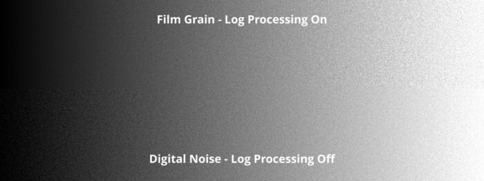
Film grain operates in almost the opposite manner of digital noise. The light-reactive particles in film are most visible when the film is clear—that is, in the brightest areas. Dark parts of the frame are more opaque, so the particles are not as obvious. Unlike a digital camera, in a film camera grain is entirely a property of the film stock, and every stock has a unique look to its grain. Since the grain's appearance can be recognized it is even more important to closely match its character when regraining a composite. Let's return to that Film Grain tool:
The default mode of the Film Grain tool emulates actual film—the grain is more prevalent in brighter parts of the picture. The tool can be made to better match digital noise by turning off the Log Processing switch. Here's a comparison of the two modes:
Noise and grain frequently have different patterns in each channel (record in film parlance). You can get independent control of each channel by unchecking the Monochrome switch in the tool. When matching grain, you should look at each channel individually while it is playing, comparing the original grain to your synthetic grain to get the best match for size, strength and distribution. There are limited controls in Film Grain to control distribution—Offset can affect how the grain mode operates in the shadows, but there is no control to reduce it in the brights for the noise mode. I sometimes use a Bitmap node to convert the luminance of my composite to an alpha, tick the Invert, and plug it into the Effect Mask input of the Film Grain.
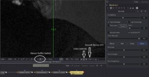 To make comparing the grain patterns easier, put your original, noisy plate into a Viewer's A buffer and the regrained composite into the same Viewer's B buffer and use the A|B split to look at them. Zoom in to 200% and turn Smooth Resize off. You don't want Fusion to interpolate anything when you're dealing with pixel-scale details. Click the A side of the image and turn the controls off to remove the line. When you can no longer tell where the division between the two images is, you can consider the grain matched!
Some additional points for handling grain: Although noise and grain are different artifacts, the techniques for handling them are similar enough that most artists use the terms interchangeably. Any time you blur an image you will likely need to regrain because the blur will have destroyed the existing grain. Grain can make an image look a little sharper and more detailed, even if there is no actual information being carried in it. If you experience banding in a subtle gradient, adding a little bit of grain will dither it, scattering the edge of the band across a wider area. A very slight Unsharp Mask right after regraining frequently improves the perception of sharpness in the image without introducing ringing.
Rolling Shutter
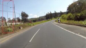
Most current digital cameras use CMOS sensors that capture the image one row at a time. This happens very fast, but there still might be a slight misalignment between the top of the frame and the bottom. In very fast pans or lateral movements, this can cause vertical lines to "lean." The result is sometimes called the "Jello effect" among drone photographers since in extreme cases it can make the image seem jiggly. Most of the time rolling shutter is not too much of a problem, but if camera tracking is going to be involved, any amount of rolling shutter can make it difficult, or even impossible, to get a solution.
The accompanying image is a somewhat extreme case, having been shot by a GoPro camera with a slow rolling shutter that was firmly mounted on a motorcycle. There are limited options for repairing such footage. Optical flow technology (available in Fusion Studio among the Dimension tools) and careful use of the Distort tool can help. There is also a Fuse available that can help to correct the problem if motion vectors (from the optical flow, usually) are available. Fuses are custom scripted tools that I will discuss in more detail in the Customization and Pipeline chapter. The Rolling Shutter Fuse is available here.
Matching rolling shutter is also difficult, but not as hard as correcting it. Usually the jello is not nearly so jiggly as in the above image, and all you need to do is introduce a little bit of shearing to your elements. That is easily done using a Grid Warp with X and Y Grid Sizes of 1. The Warp usually needs to be animated to account for variance in the speed of the camera move.
Motion Blur
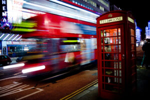
A still camera will usually express shutter speed in terms of how long the shutter is open—in seconds or fractions thereof. A film camera's shutter, however, is described with an angle, with 180º being the most common setting. A 180º shutter is open for half of the duration of the frame. At the typical 24 frames per second of film, that means the shutter is open for 1/48th of a second. Slower shutters are open longer, so the angular measure is higher. A 360º shutter is open for the full 1/24th second that the frame is in the gate (the rectangular opening that masks the film). A 90º shutter is open for only 1/96th second.
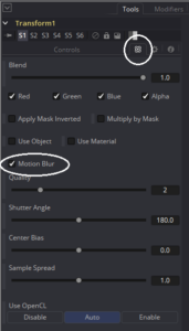 Fusion uses the same terms for its motion blur settings. Tools for which motion blur makes sense will have a switch for it in the Common Controls tab. The Quality slider determines how many samples are taken to create the blur. The other controls are usually best left at their default settings, but check the Tool Reference document for more information about them.
Removing motion blur is all but impossible, but that's okay because it has become an expected feature of the "filmic" look. High frame rates and less motion blur have become associated with low-quality productions, so it is very rare that a client will want the blur reduced.
Matching motion blur on elements is far more common, and usually fairly easy. Transforms and warps have the motion blur controls shown above built in. CG elements that need to be blurred can be rendered with motion vectors, and the Vector Motion Blur tool can perform the blurring. In cases where neither of those options are appropriate, Directional Blur, or even the Smear mode in the Paint tool, can be used to create the appearance of motion blur. Fusion Studio users also have access to the excellent Reel Smart Motion Blur plug-in.
Exposure
Cameras can capture a huge range of light levels. Unfortunately, they cannot capture that entire range all at the same time. When shooting, the DP must make a decision about how bright the image should be and what portions of the frame are to be shown most accurately. Exposure refers to the light level captured by the camera. It is influenced not only by the amount of light in the scene, but also by the shutter speed/angle, the size of the aperture, and the sensitivity of the film or sensor.
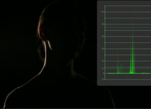 An image that is underexposed is too dark—details are lost in the shadows. In this image, I have turned on the waveform monitor, which maps the brightness of the image to the Y-axis of a graph. It is a very useful tool for measuring and matching exposure levels. Here we see that most of the information in this image is packed down into 0, or black. No matter what I do with color correction, that flat line will always be flat—the information has been lost. Even if some of that information were still there, though, if the frame was merely very dark instead of being crushed out to black, gaining it up would also raise the noise floor, resulting in an unacceptably grainy image.
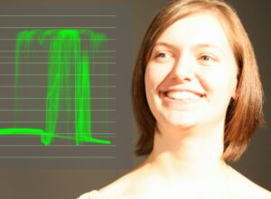 Overexposure is the opposite—information is lost at the upper end of the brightness range. When this happens, it is usually referred to as clipping—the waveform appears as though the top of it has been clipped off. In this image, there is no detail preserved in Jessica's forehead or cheek. I reduced the gain a little bit so you can see that the top of the waveform is flat and a little brighter than the surrounding wave, indicating that extra data has been packed in there. Attempting to reduce the brightness of an overexposed image usually reveals an ugly, flat gray area.
Film has historically had a much greater dynamic range (the distance between the darkest and brightest tones that can be captured at the same time) than video formats, but modern digital cinema cameras such as the ARRI Alexa or Sony F55 have largely closed that gap. The Alexa can capture approximately 14 stops of brightness. Each stop is twice the brightness, so the Alexa has a dynamic range of about 8000:1. (Your eye can perceive about 20 stops, or over 500,000:1.) A Rec.709 image has, at most, 9 stops, or a paltry 512:1, and most displays are only capable of 6 or so.
All of this extra dynamic range from a cinema camera or film is made possible first by the logarithmic storage format and second by the extra bit depth used to store it. DPX is typically 10 integer bits per channel, which is just barely enough to hold these high dynamic range (HDR) images.
The waveform monitor is a very useful tool when compositing. It allows you to see information that might be hidden by your view LUT because it's superwhite. It makes it easy to objectively adjust brightness levels so that you can be sure that, for instance, in a daylit scene nothing gets brighter than the sky.
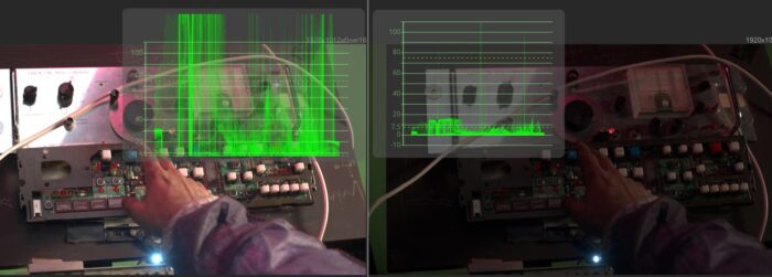
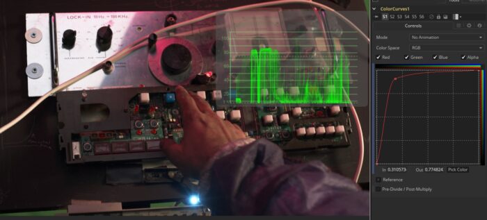
Here the waveform monitor shows us that although the scene was exposed very brightly, the only element that is actually clipping is that bright blue light at the bottom. Using that information, I used a ColorCurves tool to tonemap the brightness levels to preserve the detail in the brights while maintaining a pleasant overall exposure.
The waveform now shows a more reasonable distribution of values, and nothing is clipping. Tonemapping is used to turn High Dynamic Range images into pictures that are pleasing to the eye. Note, however, that by using this curve, the image is by definition no longer linear. This kind of operation should be the very last thing you do before saving an image intended for display.
Data Overlays
 Occasionally a shot will call for some kind of digital overlay. Satellite imagery or the point-of-view of a camcorder commonly have that kind of extra layer. Since these overlays go on after the image has been captured, they are not subject to noise, lens blurs, vignette, or any other such camera artifacts. This image is an interesting example, as the photo being taken by the phone has its own lens and sensor effects (almost none of which made it into this final comp because the client wanted a "pristine" image). The phone's interface was applied after those effects, and then the combined image needed to be integrated with the shot, getting its motion blur, grain and exposure.
Storage
On some occasions, the method used to store an image can make a difference in the composite. Lossy compression formats like Jpeg or unusual color management can create issues that you will need to compensate for.
Compression
In an ideal world, footage provided for visual effects would never be compressed. We would get the most pristine version of the image possible directly from the camera. The world is seldom ideal, though, so you're eventually going to need to learn how to deal with compression artifacts. These generally come in three flavors:
Chroma sub-sampling is a technique used to reduce the bandwidth necessary to transmit color footage. A television signal is in a color space called YUV (with several variants—YIQ, YCbCr, and YPbPr are roughly equivalent for our purposes), which places luminance in the Y channel and chrominance in the other two. Our eyes are not very sensitive to chroma differences, so it is common to reduce the resolution of the chroma channels to save on size. When you see references to 4:2:2, 4:2:0, or 4:1:1, that means the image has been subsampled. 4:4:4 means that it has not.
I won't go into the technical details of chroma sub-sampling, but I will tell you that if you want to match it, the usual method is to use a ColorSpace node to convert the footage to YUV space, slightly blur the Green and Blue channels (which are now U and V), then convert back to RGB. This will create the slightly smeary, inaccurate colors of subsampled footage.
Spatial Compression, most often seen in the form of jpeg artifacts, is a method of reducing file size by reducing the number of colors used in an image. It is difficult to match jpeg compression artifacts using Fusion tools, but you do have a very simple solution: Just prerender your element as a low-quality jpeg. Instant artifacts!
Temporal Compression is the toughest one. You might see blocky artifacts in very compressed video intended for Internet viewing. Too much stock footage is overcompressed into mp4 format, and it is up to VFX and colorists to try to bang it into shape. Usually the best you can hope for is to denoise the footage, match the blurriness as best you can, then regrain and sharpen the composite slightly.
Color Space
You must be aware of the color space of your source footage and learn how to recognize when something looks wrong. The CineonLog and Gamut tools are used to convert most footage from its original color space into linear, although some clips may come with their own custom LUT, which can usually be loaded in a FileLUT or one of the OCIO (Open Color Input/Output) nodes. Information about the color space of the footage should come from the client in the technical specifications sheet.
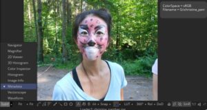 In the event that such information is not available, sometimes you can use the Metadata Sub-View to learn if there is a color profile tag. This image is in sRGB, indicated by the ColorSpace tag in the Metadata.
Dynamic Range
We talked a little about dynamic range earlier in the section on exposure. Although a camera may be able to capture 14 stops of exposure, the storage format is not necessarily capable of retaining all of it. Hopefully the production is sophisticated enough to choose a robust format, but there are times when you may still receive 8-bit images. While you can certainly place the footage in a 16-bit or higher container, that doesn't increase the amount of data that is present; it just makes your own manipulations less destructive.
Take the time to look at your footage in the waveform monitor and do some gain adjustments to find out if and where it clips. Check to see if detail has been lost in the extreme brights and darks. That will let you know what you'll need to do to your elements to get a good match.
As you can see, the intricacies of the image capture process can create a number of effects that you may have to either match or remove. Understanding how the camera operates and what happens to the image at each stage can help you make the best possible composite. Even if you are creating entirely synthetic images, treating your elements as though they came from a real camera can lend a certain pleasant aesthetic. We've been conditioned to associate some of these artifacts, such as shallow depth of field and motion blur, with professional film projects.
We're almost done! Next up is Customization and Pipelines. Learn how to adapt Fusion to best suit the way you work.
Hi, Bryan. Thank you for your generous sharing of this knowledge, but I have two questions: 1. Does the linear workflow can't use curves to correct colors, or can‘t adjust gamma parameters? For example, RGB Gamma in the CC node.
2, I learned that as a compositing artist need to learn photography, but there are many contents of photography, what should I study specifically? Look forward to your answer!
1) Gamma adjustments work on linear images, but the results will be a little different than what you expect in comparison to a gamma-corrected image. A linear image will respond more strongly to a gamma adjustment than most sRGB images. On the other hand, a sRGB image will respond more strongly to a Gain adjustment. It is sometimes useful to do a temporary gamut conversion into sRGB to color correct, then convert back to linear; the Ranges controls are particularly fiddly when you try to use them on a linear image—you sometimes have to really crunch down the low end to limit it to what you as an artist perceive as the shadows. Changing the image's gamma space first lets you use more reasonable settings. Some other operations also benefit from doing that, like glows and luma keying.
2) Pretty much anything you learn about the craft of photography is useful in compositing. After all, we're trying to simulate what happens in the camera in order to create the most believable image possible. Although I suppose the philosophical parts of photojournalism are inimical to what we do: Fooling people is the point. I guess the best things to learn are the ones that excite you the most as an artist—the experience you pick up from doing any kind of photography will inform your work as a compositor, and you're most likely to get a lot of experience quickly if you enjoy what you're doing and are trying to excel at it.
Very informative Bryan, thanks for taking your time to write such a wonderful article.
I'm glad you liked it!
Hello, Bryan. I have read the book that you write about Fusion composition. That's really helpful for me. Thanks a lot for that. I love the green screen composition, But it's hard for me because I'm a beginner and I don't have professional training. I am eager to learn a standard about it. So I am wondering if you can help me or recommend some learning resources and tutorials.
I'm really looking forward to Chapter 12 Customization and Pipeline of this book! why not go on finishing it. I think it's valuable for every composition lover.
The old Eyeon channel on YouTube is still mostly valid. Rony Soussan had a good course on FXPHd a while back; I'm not sure if that's still available or not. There was also a decent beginners course on Digital Tutors (now PluralSight) a few years ago.
As for finishing the book, it's not really worth my time to do the work until such time as BMD finishes the user interface redesign. I'm going to have to redo all the screenshots anyway (and that was always part of the plan), but I don't want to do it twice because the UX team was slow getting their job done.