This is part five in a series on OpenCL Fuse development for Blackmagic Fusion. I am attempting to convert the lessons from the Book of Shaders into working Fuses, learning a bit about programming and parallel processing as I go.
As I said at the end of the previous article, I'm skipping BoS Chapter 6 on Color because this series is aimed at compositors, who hopefully already understand that topic fairly well. If you're an engineering type, though, definitely take a look at that chapter and work through the exercises; they'll do you good! I am now moving on to drawing shapes.
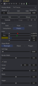
 As usual, I'm looking ahead toward where I think I'll want to expand on what I learn, so I'll begin by adding some more controls to the Fuse, even before I start looking at the OCL code. Obviously, I'll need to add another button for this mode. For now, I'll call it "Rectangle," although I might change it to "Shapes" later on and add another sub-mode multi-button like I did for the Interpolation mode. I also want some in-Viewer controls for transforming the shape, shells for which are not available in my template. To the right you can see a version of the control panel that's even a little further advanced than this article describes, with controls for Soft Edge, solid or hollow shapes, and a mode that creates a regular polygon.
I copied most of my control shells from the User Controls document at VFXPedia. Gringo seems to have overlooked the on-screen widgets, though, so I've had to extract the information I want by using the Edit Controls feature in Fusion. I suppose this will be remedial information for most anyone capable of following these articles, but I'll share it, anyway. If you right-click any node and choose "Edit Controls" you'll get a dialog you can use to add custom controls to any node, or modify existing ones. You can then copy the node and paste it into your editor to get a look at the syntax.
For my new controls, I'll need a new DataType: Point, which is a 2d vector. There are also some new parameters to look at. PC_ControlGroup and PC_ControlID work just like IC_ControlGroup and IC_ControlID, except they're for viewport widgets. Easy enough. RCID_Center and RCID_Angle let you connect the different widgets to one another so that when you, for instance, adjust the Angle, the onscreen RectangleControl tilts. Here's an example of one of my new controls:
inShapeHeight = self:AddInput("Shape Height", "ShapeHeight", {
LINKID_DataType = "Number",
INPID_InputControl = "SliderControl",
INPID_PreviewControl = "RectangleControl",
INP_Default = 0.5,
INP_MinScale = 0,
INP_MaxScale = 1,
PC_ControlGroup = 1,
PC_ControlID = 1,
RCID_Center = "Center",
RCID_Angle = "ShapeAngle",
IC_Visible = false,
})
Obviously, the new controls will also need to be included in the NotifyChanged() function, and another case added for the new Rectangle mode. And the new controls need to be imported to Process() as well. That's all been covered in previous articles, along with creating the kernel call, so I'll skip it and move straight to the OpenCL part.
The Rectangle function
The Book of Shaders offers an analogy about drawing a square on graph paper and develops it into an algorithm that uses a series of multiplied step functions to "snip off" the sides of the shape:
float left = step(0.1,st.x); // Similar to ( X greater than 0.1 )
float bottom = step(0.1,st.y); // Similar to ( Y greater than 0.1 )
// The multiplication of left*bottom will be similar to the logical AND.
color = vec3( left * bottom );
This code creates a black strip along the left side and bottom of a white screen. To get the top and right sides of the square, the coordinate system is inverted and the same procedure is used:
float top = step(0.1, 1-st.y);
float right = step(0.1, 1-st.x);
To streamline things, a 2d vector can be used instead of single floats, and all of the multiplication can be done at once:
vec2 bl = step(vec2(0.1),st); // bottom-left
vec2 tr = step(vec2(0.1),1.0-st); // top-right
color = vec3(bl.x * bl.y * tr.x * tr.y);
Translating that into OpenCL yields something very similar:
float2 bl = step((float2)(0.1f, st));
float2 tr = step((float2)(0.1f, 1.0f-st));
float3 color = (float3)(bl.x * bl.y * tr.x * tr.y);
As I said before, I immediately wanted to add controls for the center, width, and height of my rectangle so that it will function similarly to Fusion's Rectangle Mask tool. On a whim, I decided to also put in controls for making a hollow rectangle and changing its border width.
The border width control potentially creates an issue with regard to the image aspect ratio. As before, I'll normalize the screen coordinates, but that means that the non-square aspect of the image doesn't translate well into the border. For a 16:9 image, the vertical lines will be much wider than the horizontal ones. In order to correct for that, I'll need to separate the border width into a vector and modify one of the components to compensate.
//correct for image aspect ratio
float2 iborder = (float2)(border, border*imgsizef.x/imgsizef.y);
This is a common correction necessary whenever you have normalized screen coordinates.
Applying the center and rectangle width parameters is just a matter of doing some simple arithmetic in the step functions:
float2 bl = step((float2)(ctr-rectsz*0.5f), st);
float2 tr = 1.0f-step((float2)(ctr+rectsz*0.5f), st);
float pct = bl.x * bl.y * tr.x * tr.y;
Due to the mirror-split of the process, the rectsz variable needs to be divided in half in order to work right. The center control is subtracted from one side and added to the other. I moved the inversion outside the step function because it made a little bit more sense to me that way. I broke the results into their components so that they could all be multiplied into a single float value.
The final piece of the puzzle is what to do with that "solid" switch and the border width control. There are a couple of ways to go about it. The easiest one I came up with is to create a slightly smaller rectangle, invert it, and multiply it by the larger one. The border control is added to rectsz for the positive rectangle and subtracted from rectsz for the negative. This causes the border to grow at the same rate both outward and inward. Recall that I already corrected the y component of the width and stored the results in iborder.
//Create positive
float2 bl = step((float2)(ctr-rectsz*0.5f-iborder*0.5f), st);
float2 tr = 1.0f-step((float2)(ctr+rectsz*0.5f+iborder*0.5f), st);
float pct = bl.x * bl.y * tr.x * tr.y;
//Create negative
float2 bln = step((float2)(ctr-rectsz*0.5f+border*0.5f), st);
float2 trn = 1.0f-step((float2)(ctr+rectsz*0.5f-border*0.5f), st);
float pctn = bln.x * bln.y * trn.x * trn.y;
float check = pct*(1.0f-solidf*pctn);
float4 outcol = (float4)((check*col.xyz)*col.w, check*col.w);
The check variable is the final result of the process. If the Solid switch is on, then solidf contains a 0, and the main rectangle is multiplied by 1.0: no change. If Solid is off, then solidf contains a 1, and the main rectangle will be multplied by the smaller one.
In the last line, there's a little juggling going on to premultiply the RGB colors. Simply multiplying by col actually gave the wrong results. I'll have to go into all the other modes and do the same thing. It's a little odd to use .xyzw to mean RGBA, but unlike GLSL, OpenCL doesn't have .rgba aliases for color components. Everything is treated like a spatial coordinate.
Here is the completed rectangle() function:
kernel void rectangle(FuWriteImage_t img, int2 imgsize, float4 col,

float2 rectsz,
float2 ctr, float angle, float border, int solid)
{
int2 ipos = (int2)(get_global_id(1), get_global_id(0));
float solidf = 1.0f - convert_float(solid);
//normalize the pixel position
float2 iposf = convert_float2(ipos);
float2 imgsizef = convert_float2(imgsize);
float2 st = iposf/imgsizef;
//correct for image aspect ratio
float2 iborder = (float2)(border, border*imgsizef.x/imgsizef.y);
//Create positive
float2 bl = step((float2)(ctr-rectsz*0.5f-iborder*0.5f), st);
float2 tr = 1.0f-step((float2)(ctr+rectsz*0.5f+iborder*0.5f), st);
float pct = bl.x * bl.y * tr.x * tr.y;
//Create negative
float2 bln = step((float2)(ctr-rectsz*0.5f+border*0.5f), st);
float2 trn = 1.0f-step((float2)(ctr+rectsz*0.5f-border*0.5f), st);
float pctn = bln.x * bln.y * trn.x * trn.y;
float check = pct*(1.0f-solidf*pctn);
float4 outcol = (float4)((check*col.xyz)*col.w, check*col.w);
FuWriteImagef(img, ipos, imgsize, outcol);
}
The Ellipse Function
The Book of Shaders provides four methods for creating a radial distance field. Three of them are really the same method under the hood: distance(), length() and the Pythagorean Theorem are all the same thing, just with more and more of the math defined explicitly. The fourth method, the dot product between two vectors, is an entirely different kind of math altogether. Having recognized that the first three methods are all the same, I won't bother trying each one out; I am content with the knowledge that distance() is the most straightforward approach.
The big difference between what I am doing and what BoS does is that BoS assumes a square canvas, whereas my Fusion defaults are for a 16:9 frame. I immediately have to deal with an aspect ratio issue, and I have to admit that I do not quite solve it to my satisfaction here.
float st = distance(ctr, st);
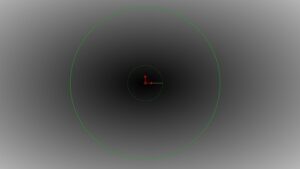
 That is the most basic form of the algorithm. Distance() calculates the straight-line distance between two points and returns it as a single float value. As usual, st is the local pixel, and ctr is the position of the Center control provided by the Fuse. Using this formula creates a distance field: an image in which the value of a pixel indicates how far away it is from the Center control. I expect this concept will come into play a good deal later on.
If you look carefully at that image, you can see the aspect ratio problem. The dark center is ellipsoidal, stretched in the x-direction. It took a bit of experimentation to figure out exactly how to solve that. I stretched and squashed both my center reference and the local pixel position without success. Eventually I realized that the 0,0 coordinate was in the lower-left of the screen, but all of my operations were assuming that I was operating from the center of the screen. Once I had that epiphany, I knew that I had to move the world, do my stretching, then move it all back.
//Correct for aspect ratio
st.y = ((st.y - ctr.y) * imgsizef.y/imgsizef.x) + ctr.y;
That line corrects the y-coordinate of the local pixel, stretching the distance field into a circular aspect. I initially did this procedure on the x-coordinate, but Fusion always applies aspect corrections to the y-axis, so my first attempt made the eventual circle the wrong size.
The next step is to threshold the distance field with a step() function in order to get the shape. Notice, however, that the distance field is dark in the center. A step() will therefore create a black circle on a white field, while we want it to be the other way around. Inverting is as easy as subtracting the result from 1:
float pct = 1.0f - step(0.5f, distance(ctr,st));
That creates a circle with a diameter equal to the screen width. Obviously, I'll want to control the size of the circle with my controls, so now I need to figure that out. Having learned from my difficulty with the aspect ratio, I decided that instead of trying to manipulate the distance field itself I would use the control to scale the coordinate system.
st = ((st - ctr) * 1.0f/(ellipsesz+0.0000001f) + ctr;
Subtracting the center moves the middle of the distance field to the origin, then the coordinate system is scaled by the ellipsesz parameter. Since I'm stretching the world instead of the ellipse itself, I use the reciprocal of the widget's size. I'm always a little leery of having a variable as the denominator of a fraction, so I added a tiny value so that I could never divide by zero. After the stretch, I move the coordinate system back to its original location by adding the Center position.
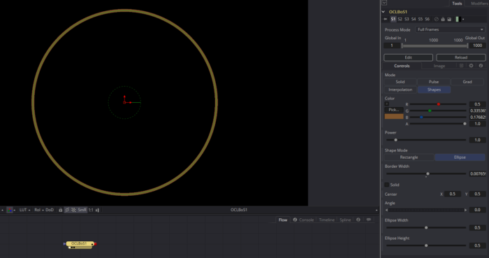
This is, perhaps, an unconventional approach to the problem, but it works. I wonder, though, if this method is what causes the aspect ratio distortion I see when I turn the solid mode off. To do that, I'll use the same technique that I developed for rectangle().
float pos = 1.0f - step(0.5+border, distance(ctr, st));
float neg = 1.0f - step(0.5+border, distance(ctr, st));
float pct = pos * (1.0f - solidf * neg);
This is where my aspect problem raises its head. The border width is proportional to the width and height of the ellipse. If it's wider than it is tall, the border is thicker in the x direction. This happens because I'm actually scaling non-proportionally instead of drawing a line with consistent width.
The remainder of the function is similar to the other one, except that I refined the color assignment a little bit to make it more comprehensible:
float3 rgb = (float3)(pct * col.xyz); //Set RGB
float4 outcol = (float4)((rgb)*col.w, pct*col.w); //Premultiply
For the finished function, please take a look at the new version of the Fuse:
The Dot Product Method
As I mentioned earlier, BoS also offers an algorithm based on a dot product. My understanding of linear algebra is still embryonic, so I don't know that I fully comprehend what's going on here.
float2 dist = st - ctr;
float radius = ellipsesz.x *0.5;
float pct = 1.0f - smoothstep(radius-(radius*0.01f), radius+(radius*0.01f),
dot(dist, dist)*4.0f);
This code is adapted direction from the BoS example. The dist variable is fairly straightforward—it's just the difference between the current pixel location and the Center control. The Ellipse's Width control is a diameter, so dividing it by two should give the radius. If I turn off my scaling line from earlier, I do indeed get a circle that fills the widget.
I pretty well understand the smoothstep(), too. The first two arguments give a slightly blurry edge. With a couple more controls, that could be a nice feature: Blur outward and blur inward, maybe with a switch that links them so they act the same as Fusion's Soft Edge controls. The sticky bit is that dot product and the multiplication by 4. My understanding is that the dot product of a vector by itself should produce the square of its length. Which would mean needing a sqrt() function again, which is what we're trying to avoid. And why multiply by four?
My guess is that it's just a bit of a cheat to make the circle fit in the canvas. Indeed, if I put the sqrt() in there, remove the *4.0, and set the radius to 0.5, the circle fills the canvas on the BoS page. Since I need my circle to exactly fill my on-screen widget, a "Looks About Right" solution won't work. And since the point of the dot product method is to eliminate the sqrt() for the sake of speed, there's really no point in using it here.
Update: In the comments, Chad points out that 0.52 * 4 = 1.0, so the dot product does eliminate the sqrt() if you're not too lazy to think it through. I am still in the midst of writing the next article, so I'll apply that new understanding when I get to the point of rewriting my ellipse kernel.
The smoothstep() would probably be a good addition, but I think I'd rather use a proper anti-aliasing function instead if I can find one.
There is some more interesting stuff to learn in the BoS Shapes chapter, but I think I'll leave those for another day. Next time I'll move on to Transformation Matrices.
<< Previous Article — Interpolation
Next Article — Transformations >>

dot(dist,dist)*4 is the radius (.5) squared (.5*.5 = .25) quadrupled (.5*.5*4 = 1)
Ah! Thank you! And with what I've been learning about transforming the coordinate space in the next chapter, that actually *does* work out. Cool!